Identify Both Ends and the Installation Position
Actual mating dimensions, wall type, male or female direction, insertion depth, overlap, lock and neighboring part references are recorded at both ends of every replacement fitting.
Wholesale Stove Accessories
Each spare is tied to a controlled stove-and-flue family and installation position: elbows reproduce route geometry, dampers reproduce an authorized control assembly, and adapters or fittings restore a documented interface and function.
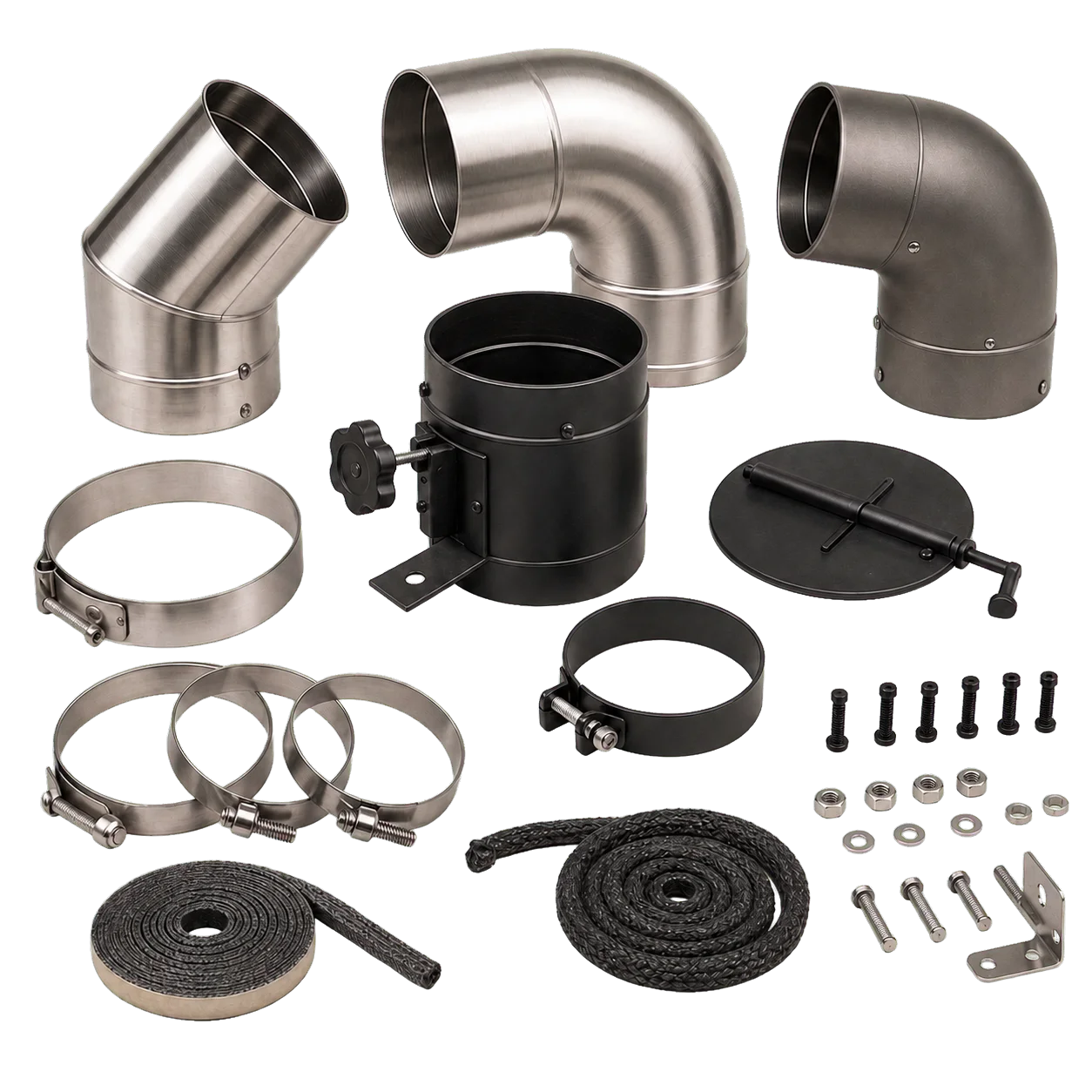
Product Focus
Matching nominal diameter does not establish wall construction, insertion direction, overlap, lock or installed duty. An elbow also changes route and support reactions, while a damper changes flow resistance and operating responsibility. Selection therefore starts with the original part reference and complete system position.
Actual mating dimensions, wall type, male or female direction, insertion depth, overlap, lock and neighboring part references are recorded at both ends of every replacement fitting.
Bend angle, centerline radius, plane or rotation and installed length are checked against surrounding sections, supports, passages and inspection access rather than treated as a standalone shape.
Blade profile and clearance, shaft location, handle orientation, open and restricted stops, position indication and accessible travel follow the appliance and flue configuration that authorizes its use.
Design Details
The replacement is matched to its exact flue position and, where applicable, through its complete operating movement.
Each end is matched to the controlled adjoining part for dimensions, wall, direction, depth, stop, overlap, lock and soot-path continuity.
Angle, centerline radius, rotation, offsets, formed seams and effective installed length are checked with route restraints, supports and service clearances.
The assembled control is checked for the specified open and restricted positions, indication and accessible handle travel without claiming a universal draft or efficiency result.
Permanent or packaging identification links the part to the appliance, pipe family, drawing revision, route position and replacement instructions so visually similar systems are not mixed.
Specifications
The specification connects every service part to a named appliance, pipe family, adjoining components, exact installation position and controlled original function.
Materials & Finish
Hot gas exposure, joint movement, mechanical control and user contact are documented separately across the complete service part.
Alloy or specification, wall thickness, formed or welded seams, mating ends, surface condition, corrosion exposure and cleaning method are stated for the named pipe family without implying universal interchangeability.
Steel grade, wall, bend or adapter forming, seams, coating location, temperature limit and joint interfaces are recorded for the supported system duty.
Material, section, clearances, shaft support, fasteners or retainers, stop geometry, position marking, handle or grip exposure and model-specific replacement references are confirmed as one assembly.
Applications
The relevant spare follows the original system family, position and installation responsibility rather than serving as a universal route modification.
A lightweight elbow, adapter or authorized damper is limited to the matched stove, pipe sections, stove-jack relationship, supports, terminal and supervised shelter instructions.
A fixed-installation spare requires the original system duty, structural supports, passages, clearances, inspection access and applicable installation requirements to remain satisfied.
Stable part codes, route diagrams, two-end interface drawings and revision-controlled packs allow buyers to restore the original configuration without substituting a visually similar nominal-size fitting.
OEM & Private Label
Development starts with original parts, drawings and route schedules and preserves a distinct functional record for each elbow, damper, adapter or service fitting.
FAQ
A valid replacement restores an identified system position and function; nominal diameter, apparent angle and visual similarity are insufficient.
Not necessarily. Actual mating dimensions, wall, joint direction, insertion depth, overlap, lock, angle, radius and orientation can all differ between pipe families.
Please provide both end interfaces, bend angle, centerline radius, rotation or plane, offsets, effective installed length, adjoining sections and the route and support drawing.
No. The appliance and complete flue system must authorize the damper type, position and operating range; adding flow resistance is not a universal upgrade.
The record includes pipe family and interior, blade profile and clearance, shaft and supports, handle orientation and accessible travel, open and restricted stops, position indication and original part revision.
Use the appliance, pipe family, original part number, route position, adjoining component codes and drawing revision rather than selecting from appearance or nominal diameter.
Please provide original drawings or samples, appliance and pipe family, route position, both interfaces, part function and geometry, materials, control details if applicable, quantity, branding and destination market.