Route Drawing from Appliance to Terminal
Stove outlet, installed height, straight runs, elbows, offsets, structure passages, support locations and terminal are shown in sequence.
Wholesale Stove Accessories
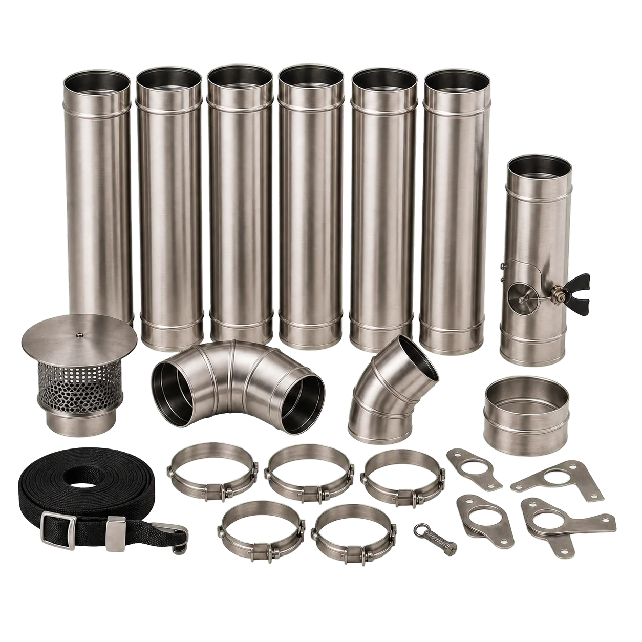
Each kit is tied to one controlled installation route and bill of materials, so every starter, straight, offset, restraint, passage and terminal component has an identified position and quantity.
Product Focus
A carton can contain many pipe sections and still be unusable if the starter, support, passage or terminal does not match the installation. The final kit is therefore reconciled against a route drawing, numbered component schedule and destination-specific installation responsibility.
Stove outlet, installed height, straight runs, elbows, offsets, structure passages, support locations and terminal are shown in sequence.
Adapters, clamps, brackets, flashing or stove-jack parts, weather or spark terminals and service components carry individual quantities and references.
Part code, route position, orientation, quantity, revision and packing location make omissions and cross-family substitutions visible before shipment.
Design Details
The kit is followed from the appliance outlet through each numbered component to the terminal and final packing position.
Appliance collar, adapter, first-section orientation and the controlled pipe family are confirmed before the remaining route is scheduled.
Installed lengths, elbows, transitions and structural restraints are assigned positions and quantities against the route drawing.
Flashing or stove-jack interfaces, caps, arrestors, weather parts and cleaning access are included only where the named route requires them.
The shipped BOM is reconciled in installation order; any site change triggers route, support, clearance and component confirmation rather than improvised use of spare pieces.
Specifications
The specification links the named stove and system family to a controlled route drawing, complete component schedule, packing record and installation context.
Materials & Finish
Flue-facing sections, load-bearing restraints, passage components and exterior terminals receive separate material and duty records within the kit.
Each section grade, wall thickness, seam, joint, installed position, temperature duty and system reference are listed rather than covered by one generic stainless claim.
Steel grade, wall, seams, coating locations and limits, mating parts, storage and route positions are documented for the named system.
Bracket loads and attachment, flashing or stove-jack interface, terminal materials, weather exposure and service references are stated by component.
Applications
The kit is relevant where the appliance, installed path, structure, terminal and installation responsibility can be documented before packing.
A shelter kit records stove, pipe family, stove-jack interface, every section and restraint, terminal, assembly order and supervised-use boundary.
A fixed-site kit is scheduled against building structure, supports, passages, clearances, terminal and qualified installation requirements.
A distributor can supply a complete route only where appliance, drawing revision, BOM and mating interfaces match the original documented system.
OEM & Private Label
OEM planning for flue kits begins with the selected route drawing, then defines sections, supports, terminal selection and packaging sequence.
FAQ
Completeness is defined against one controlled route drawing, component BOM, system family and installation context.
The reconciled BOM contains every starter, straight, transition, offset, restraint, passage, terminal and service component shown for the controlled route and revision.
No. Installed height, offsets, structure, passage, support, clearance, terminal and destination rules vary by site.
Only explicit complete-system compatibility supports mixing; nominal diameter or similar appearance is insufficient evidence.
The drawing identifies appliance and outlet, every section and joint, installed dimensions, offsets, supports, structure passages, terminal, clearances and inspection access.
Part codes, route positions, orientations, quantities and revisions are checked against the BOM, then protected and arranged by the documented installation sequence.
The development record includes stove and pipe family, controlled route, mating interfaces, supports, passages, terminal, wall and material system, site context, quantity and destination.